Navigating a starship
| Academy Library |
|---|
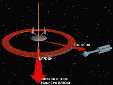
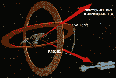
When specifying spacecraft flight paths, there are five standard modes of input available. This section looks at the five main types of input. It also explains the system of describing destinations by use of bearngs and azimuth/elevation angles. Destination Planet or Star SystemAny celestial object within the navigational database is acceptable as a destination, although the system will inform Conn in the event that a destination exceeds the operating range of the spacecraft. Specific facilities (e.g. Orbital space stations) within the database are also acceptable destinations. Destination SectorA sector identification number or sector common name is a valid destination. In the absence of a specific destination within a sector, the flight path will default to the geometric center of the sector. Spacecraft InterceptThis requires Conn to specify a target spacecraft on which a tactical sensor lock has been established. This also requires Conn to specify either a relative closing speed or an intercept time so that a speed can be determined. An absolute warp velocity can also be specified. Navigational software will determine an optimal flight path based on specified speed and tactical projection of target vehicle's flight path. Several variations of this mode are available for use during combat situations. Relative Bearing (see below)A flight vector can be specified as an azimuth/elevation relative to the current orientation of the spacecraft. In such cases, 000-mark-0 represents a flight vector straight ahead. (See diagrams below for information.) Absolute HeadingA flight vector can also be specified as an azimuth/elevation relative to the centre of the galaxy. In such cases, 000-mark-0 represents a flight vector from the ship to the centre of the galaxy. Galactic CoordinatesStandard galactic XYZ coordinates are also acceptable as a valid input, althoughare rarely used by personnel as this method is very cumbersome Using Azimuth/Elevation Angles and BearingsThis section attempts to explain course plotting for a Relative Bearing (described above). As can be seen the flight vector is specified relative to the direction the ship is heading in, using two seperate, perpendicular 360 degree axes, known as bearing and mark. Another possibility is to use Absolute Heading (described above) in this case, instead of 000-mark-0 being in the direction of the ships travel, it is the direction from the ship to the centre of the galaxy. Fig.1: Flight Vector 301-mark-000 Fig.2: Flight Vector 019-mark-038 Fig.3: Flight Vector 329-mark-322 |
| REV SD 239108.17 |
|---|


